Icom IC-9700 PTT Breakout Mod (or, “the parts Icom forgot”)
If you’ve used the IC-9700 with amplifiers, you no doubt realized that it would have been convenient if Icom would have provided a separate PTT output signal for each band. For about 5 dollars in parts they could have done this, but you can too with the mod I will describe here. This mod is quite simple and is accomplished 100% in hardware. It does not utilize CAT or any software. It does require you to open up your radio and solder a few wires onto the main board though. If that makes you a little queasy, then perhaps this is not for you and the offering by The DX Shop may be more your speed.
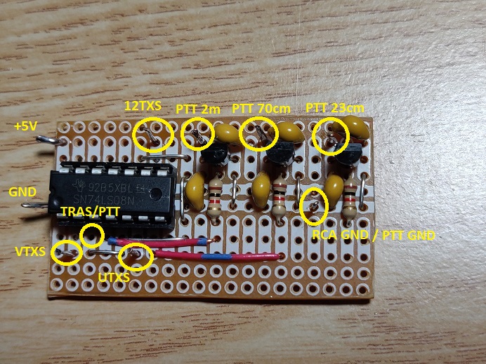
Like any other Icom radio, the IC-9700 has internal transmit (and receive) signals for each band in order to energize the appropriate transmit circuits when it is time to transmit. These signals are VTXS for VHF, UTXS for UHF, and 12TXS for the 23cm band. Only one of these signals will be a logical high when the radio goes into transmit, depending on the band selected. If we combine each of these transmit signals with the PTT signal utilizing a simple AND-gate we can provide a separate PTT signal for each band. Each AND-gate can then drive a transistor to complete the PTT circuit. Below is the schematic of this very simple circuit:

The image above only shows only the circuit for the 23cm band, but if you click on the image a separate browser tab will open with a PDF version of the complete schematic for all bands.
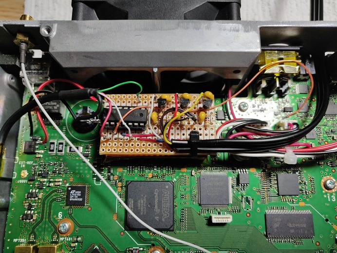
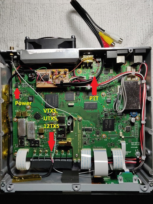
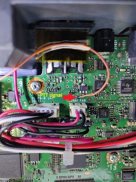
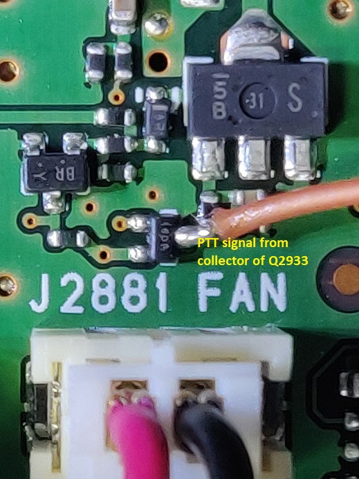
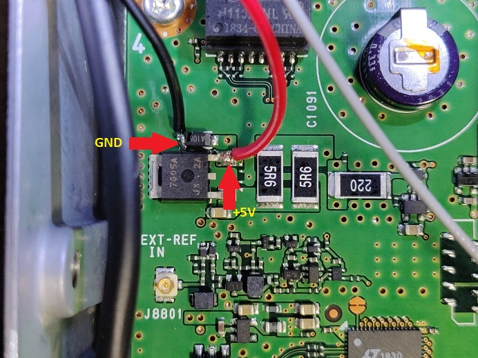
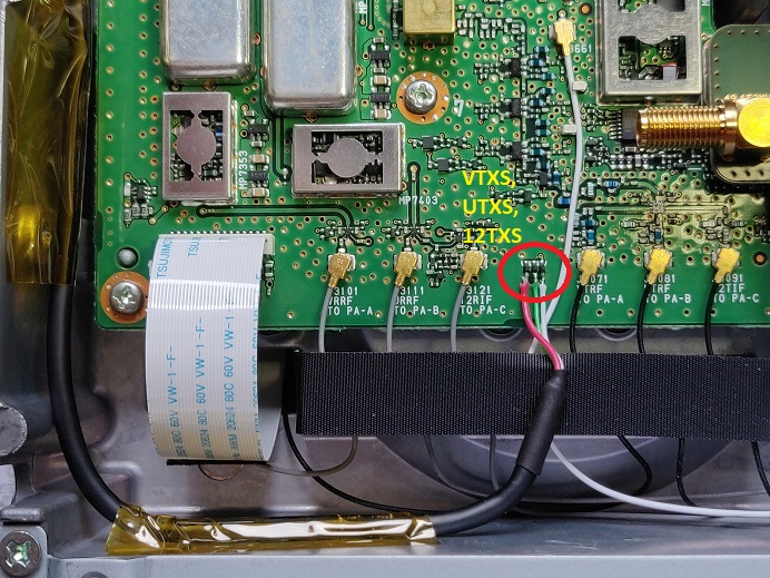
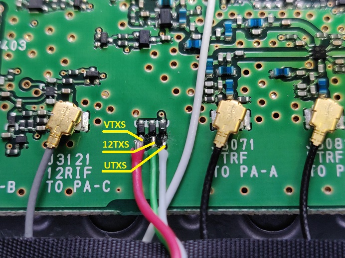
As you can see, the circuit is very simple. The capacitors at the base and collector if the transistor are there to bypass any RF that may be present on the PTT keying line. The 2N3904 transistor switching circuit is identical to the existing PTT circuit in the radio, and it can switch the same current and voltage as originally specified for the radio. For the AND gates we can use a 7408 IC that will have 4 of these gates. To power the 7408 we can tap 5V from a 5V regulator in the radio, IC 1221. The PTT signal can be tapped of the collector of transistor Q2933. Icom made it very convenient for us to tap the VTXS, UTXS and 12TXS signals. VTXS is available on the anode of diode D3032, UTXS on the anode of diode D3033, and 12TXS is available on the anode of diode D3031. These diodes are conveniently grouped together on the top of the main board.
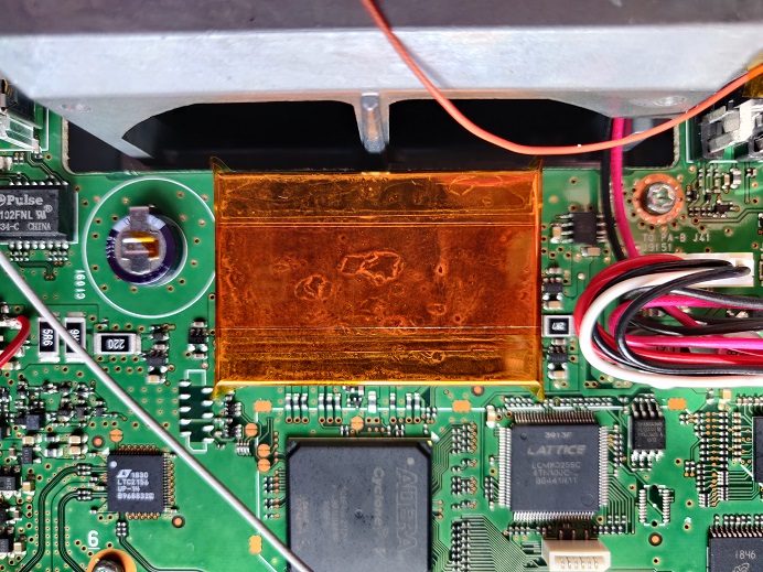
I built the circuit on a piece of perf board and mounted that with some double sided tape on the shielded box in front of the fan. I applied Kapton tape first on the shielded box just to make sure that the circuit board is well insulated, but it is not really necessary if the double sided tape is thick enough. All the signals, including power, can be tapped from the main board without having to take anything out of the radio. The images below will show you the details on how I mounted things in my IC-9700.
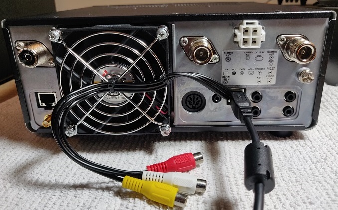
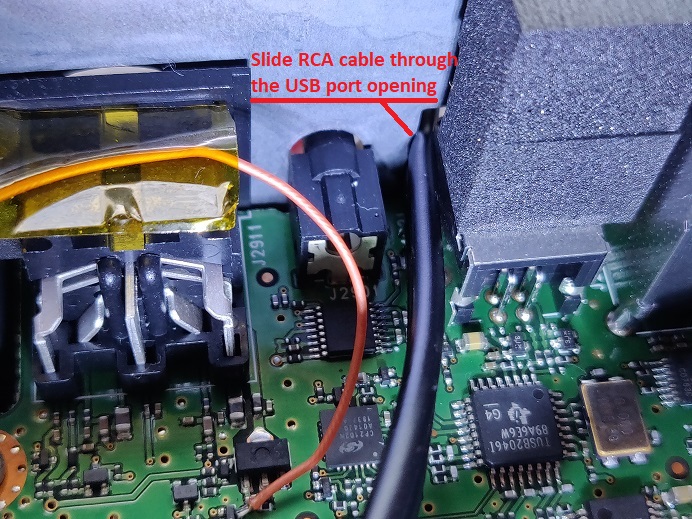
If you have a well stocked junque box you may have all the parts already, but you if you don’t, all parts can be sourced from Amazon or eBay. The cable that carries the VTXS, UTXS and 12TXS signals is just a piece of shielded USB cable. I used a flat audio/video RCA cable with female connectors for the PTT outputs. This cable will fit easily through the opening next to the USB port. It will not interfere with the USB port.
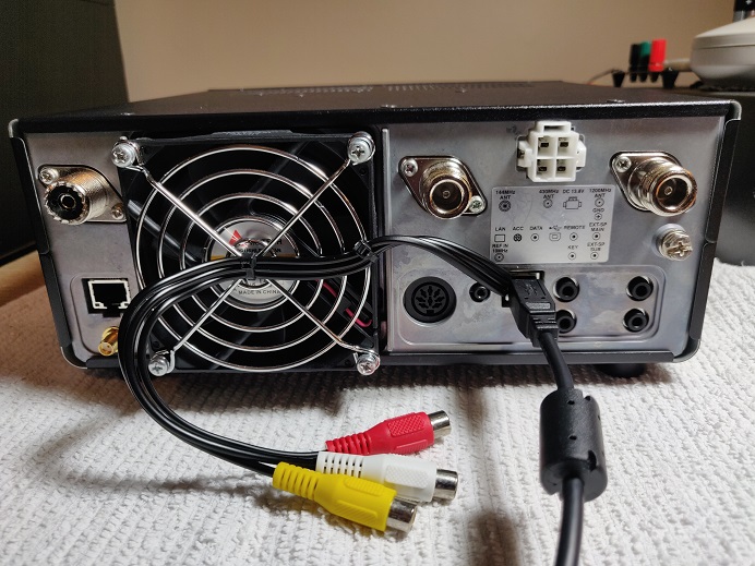
I tied the RCA cable to the fan guard with some small wire ties to provide strain relief.
I originally developed this circuit in August of 2020. A video of the prototype can be found on YouTube. The correct timing of the signals have been verified with a Siglent DSO. For a little over a year now I have been using it in many contests and weekly nets with Gemini 2m, 70cm and 23cm amplifiers, and also a VHF Design 23cm amplifier, and it never failed. The convenience of having separate PTT signals available per band can hardly be overstated. I forget that it’s even there.
Of course, as with any mods to your radio such like this one, do this at your own risk. You cannot hold me responsible for any damages you cause to your radio.

