Fox Delta ST2 / LVBTracker Calibration Mods
I modified the Yaesu G-450(XL) rotator to add remote control and it works nicely with the Fox Delta ST2-USB controller. However, I found that the control voltage, tracking the position of the antenna array, was far from linear.
The LVBTracker firmware that the Fox Delta utilizes, only allows for two calibration points, a minimum and a maximum, and together with the rotation degrees range information (360 or 450 degrees) it calculates in what position the rotator is in given a certain voltage. That probably works fine for most rotators, but it wasn’t sufficient for my modified rotator controller.
The effect of a non-linear control voltage can be that if the controller instructs the rotator to move 20 degrees in the first quadrant, it may move 30 degrees, and perhaps even 40 degrees in the third quadrant. I thought that if I could have more than two calibration points I could probably make the the Fox Delta controller track the rotator much better. Time to look at the firmware!
The great advantage of Open Source software is that you can modify the software to fit your own needs and perhaps add something of value for others. Luckily, the original developer of LVBTracker, Howard Long, G6LVB, and the Fox Delta ST2 producer, Dinesh Gajjar, VU2FD, have made the source code for the LVBTracker firmware available, for which I am very thankful!
I downloaded and installed the MPLAB X IDE and the CC5X compiler and started looking at the code. The 16F876A PIC that is used in the controller has limited code space available, but I figured that if I move some code around I would have just enough space available to allow for calibration points every 90 degrees. The overlap that the Yaesu rotator allows between 360 and 450 degrees would be lost, but that’s an easy sacrifice to make for more accurate aiming, and it would just behave like any other 360 degree rotator.
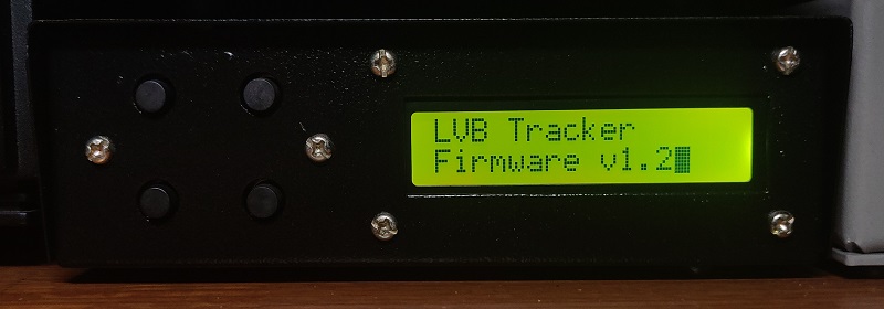
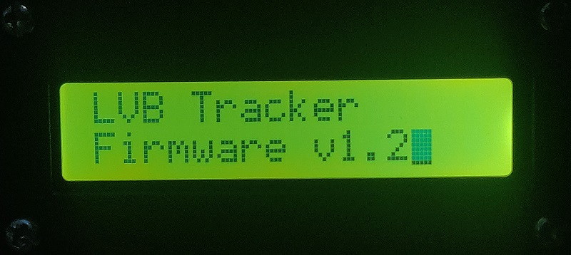
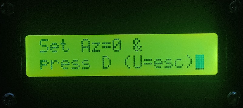
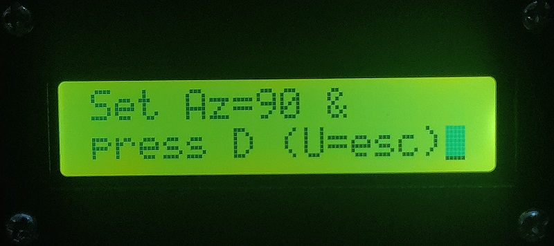
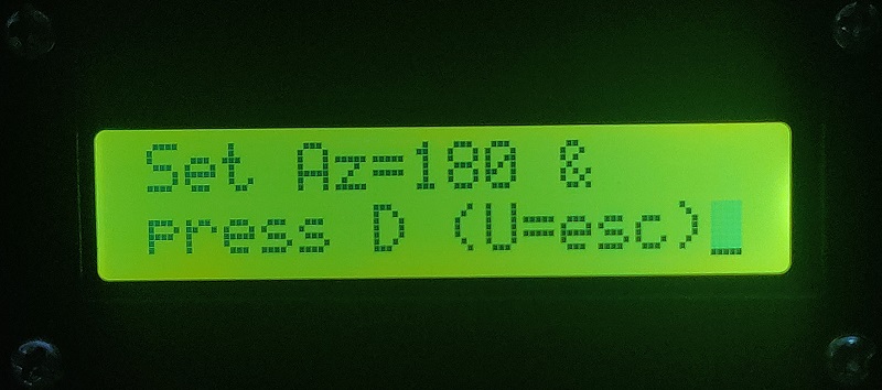
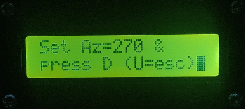
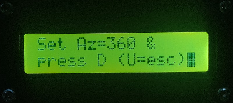
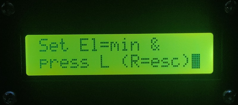
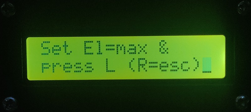
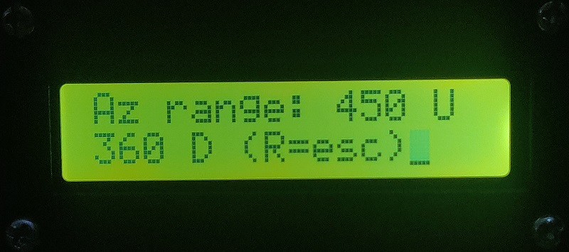
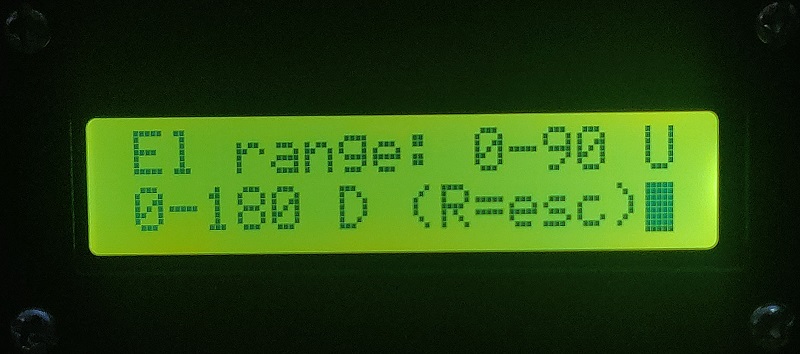
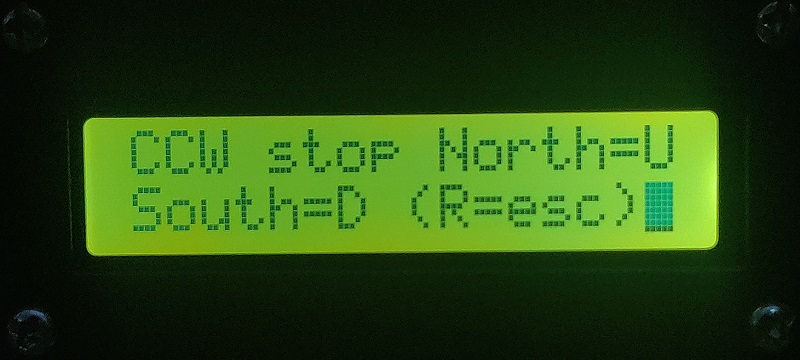
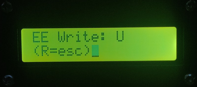
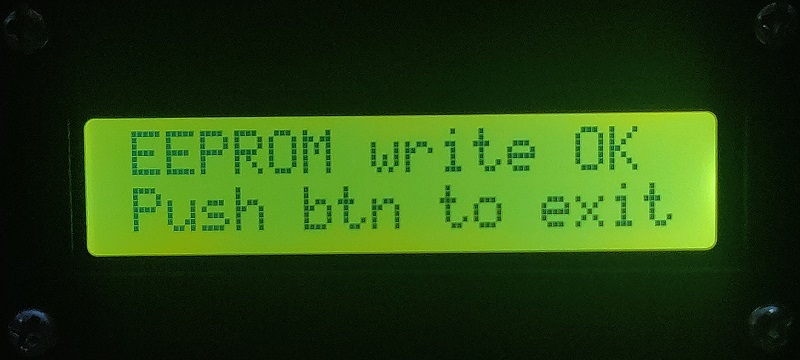
The modifications I made allow for calibration points at 0, 90, 180, 270, and 360 degrees. The images below show what the calibration procedure looks like.
The calibration procedure can be started by pressing one of the buttons on the controller while turning it on.
Apropos turning on the controller. If you have one of these Fox Delta ST-USB controllers you know that it has no on/off switch. So if your controller is hooked up to a powered USB hub, like mine is, then it’s always on, unless you can turn the USB port off on the USB hub.
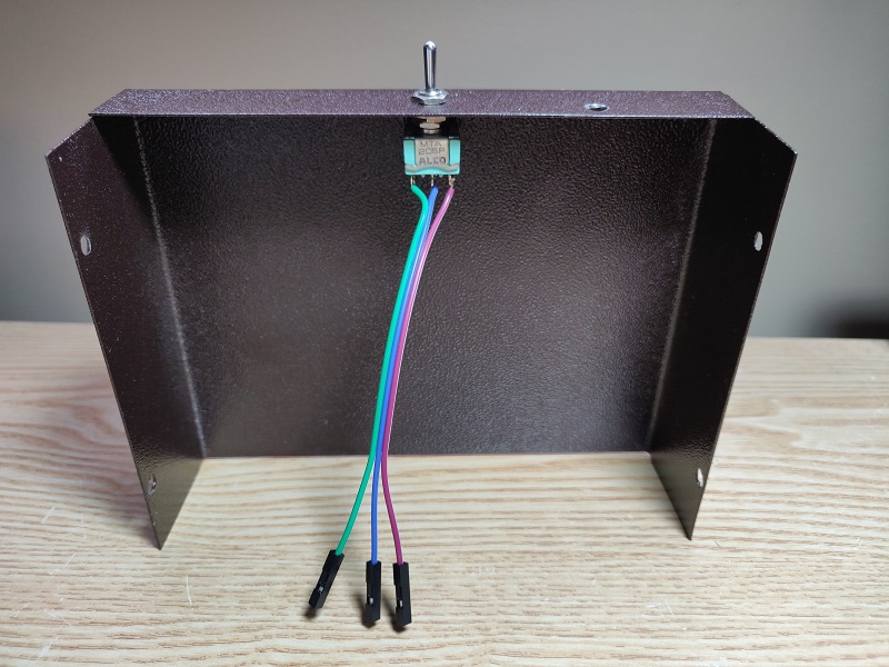
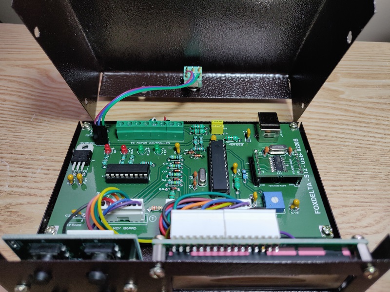
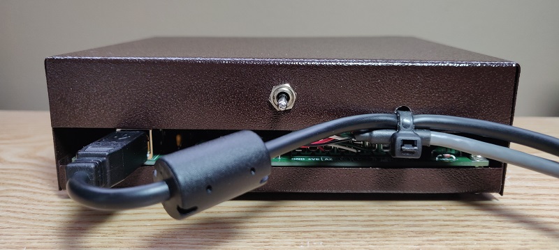
The nice thing about the Fox Delta ST2-USB controller is that it does have a provision to add an on/off switch. You can use the three pin header on the PCB that allows you to select where the +5V is obtained from, USB or Rotor. If you add a switch instead of a header shunt, you have the ability to turn the controller on and off on the controller itself. I mounted the switch on the rear of the controller because the switch I had in my junque box is too large to be mounted on the front panel. I also drilled a hole on the rear panel so I could add some strain relief to the rotator control cable and the USB cable by tying these cables to the enclosure with a zip tie.
Before I forget! I also changed the configuration bits in the program for the 16F876A PIC so that BOR (Brown Out Reset) is enabled. This was disabled in the original firmware of the Fox Delta ST2-USB code. This does not have to be a problem, but enabling it can prevent problems. I noticed that sometimes when I turned on the controller it would tell me that there was bad data in the EEPROM, and then I would have to go through the calibration procedure again. If the power supply rises too slowly to 5V on power up and the program reads from the EEPROM when the supply voltage is still too low, it could actually be writing to the EEPROM instead of reading it! So it would corrupt the data in the EEPROM. With the BOR enabled the program cannot write to EEPROM when the supply voltage is too low, and can so prevent the EEPROM data from being corrupted at power on.
The project with the source code that includes my modifications is available at GitHub.

