
Yaesu G-450(XL) Remote Control Option
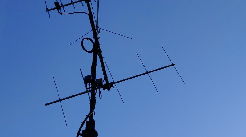
When I first started working the satellites I mounted a 2m and 70cm beam at a 15 degree elevation atop a Yaesu G-450XL rotator. It worked well, but after a while it became a little tiring to keep the antennas aimed at the satellites while at the same time trying to tune in stations on linear satellites. While searching for a solution online, I found the Fox Delta ST2-USB controller interface. This controller interface is a very cost effective solution that allows you to interface your rotator with a computer (a Raspberry Pi 4B in my case) so that the satellite tracking software can aim the antennas to the satellite for you. There was a small problem however. The Yaesu G-450XL rotator I am using does not have a remote control option! It can only be operated using the left and right switches on the front panel of the controller. So it was time to get creative and add the missing option.
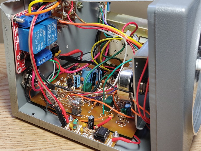
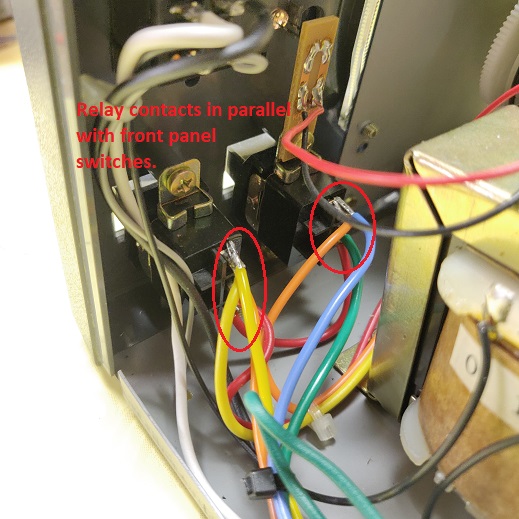
For the ST2-USB to be able to control the rotator it needs to be able to send a left and right signal to turn the rotator and it needs to receive a signal between 0 and 5 Volts that indicates what the current position of the rotator is. We could take two relays and put their normally open (NO) contacts in parallel to the left and right switched on the front panel. This would keep the manual switches functional. In addition to the relays we’d also need a circuit that takes the signals from the ST2-USB controller to actuate the relays. Now I could design something myself, but these days there are quicker and cheaper solutions available. I ordered two relay boards from Amazon that are perfect for this application. Just provide 12V and the trigger signals and wire up the relays to the switches and you’re done. These boards even allow you to select if you want to use a low or high level to trigger the relays. We will need to select “low” with the jumpers for our application. For about $3 per board it is a no-brainer to use this solution. The board can easily be mounted inside the controller on the rear panel.
Relay board mounted inside the controller. 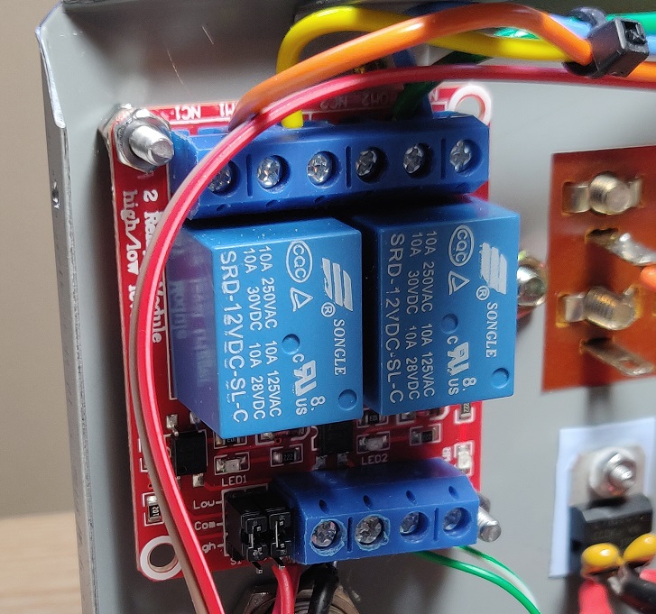
Closeup relay board
Next we’ll need to provide the ST2-USB controller with a signal between approximately 0 and 5V that indicates what the current position of the rotator is in. The Yaesu rotator controller does not provide this like the more expensive controllers do. Because the potentiometer that is inside the rotator is part of a Wheatstone bridge circuit inside the controller you cannot just tap the wiper voltage from this potentiometer. The reason for this is that the terminal voltage on the potentiometer is not constant with respect to ground as you may expect in ordinary circuits. So both the voltage on the terminal and the wiper will vary depending on the state the bridge is in, and not just based on what position the potentiometer is in. What we need to do is to measure the difference between the terminal and wiper voltage and translate that to a voltage between 0 and 5 Volts. This can be accomplished with a differential amplifier circuit. To explain how a differential amplifier circuit works is a bit outside the scope of this article, but you can check out this link for an explanation. This is the differential amplifier circuit that I used:
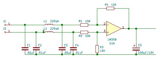
When you click on the image above a PDF file with the complete schematic of the remote control circuit for the Yaesu G-450XL will open up in a separate tab. The complete schematic will show you how to connect everything together.
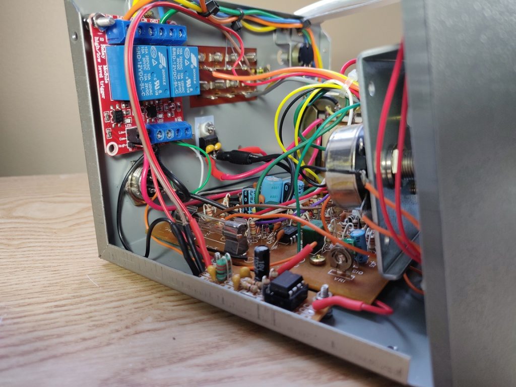
Capacitors C1-4 together with L1 and L2 form a RF filter circuit that will make sure that only DC gets passed onto the differential amplifier. Any RF on the input of the opamp would result in erroneous signals on the output, making sure that the voltage reading would be unreliable. The electrolytic capacitor on the output is there to smooth out the output signal. When the potentiometer in the rotator ages and perhaps corrodes it may display some resistance jump while it rotates. You don’t want this to upset the controller and make it trying to correct for that. The capacitor will average out these voltage jumps as a result of the resistance jumps. The amplifier was built on a piece of perf board and mounted inside the controller on the bottom.
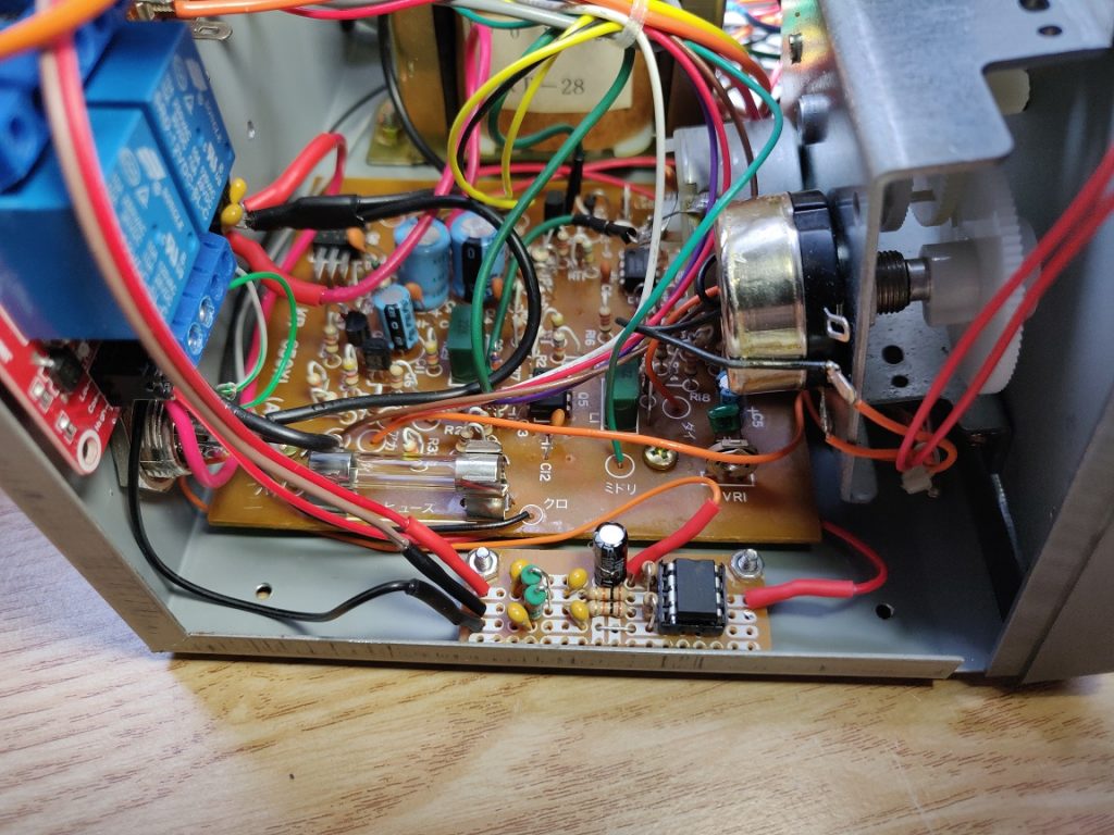
Differential amplifier mounted in controller. 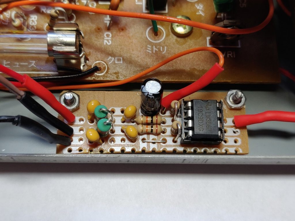
Closeup differential amplifier board. 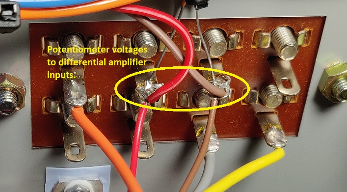
Differential amplifier inputs.
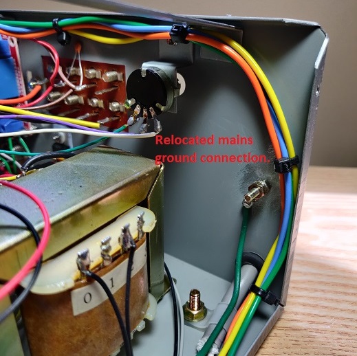
The differential amplifier and the relay board will need a 12V supply voltage. The Yaesu controller does not provide this. What we can do is take the voltage from the positive side of the bridge rectifier in the controller and feed that to a L7812 voltage regulator.
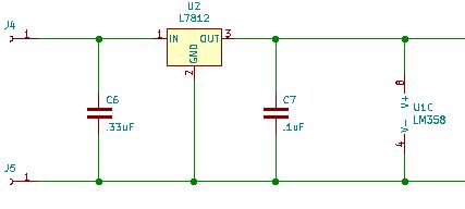
The ground of the regulator should be attached to the 0V center tap on the power supply transformer in the Yaesu controller. The voltage regulator with both capacitors can easily be mounted on the rear of the controller (insulated) so that the controller case acts as a heatsink.
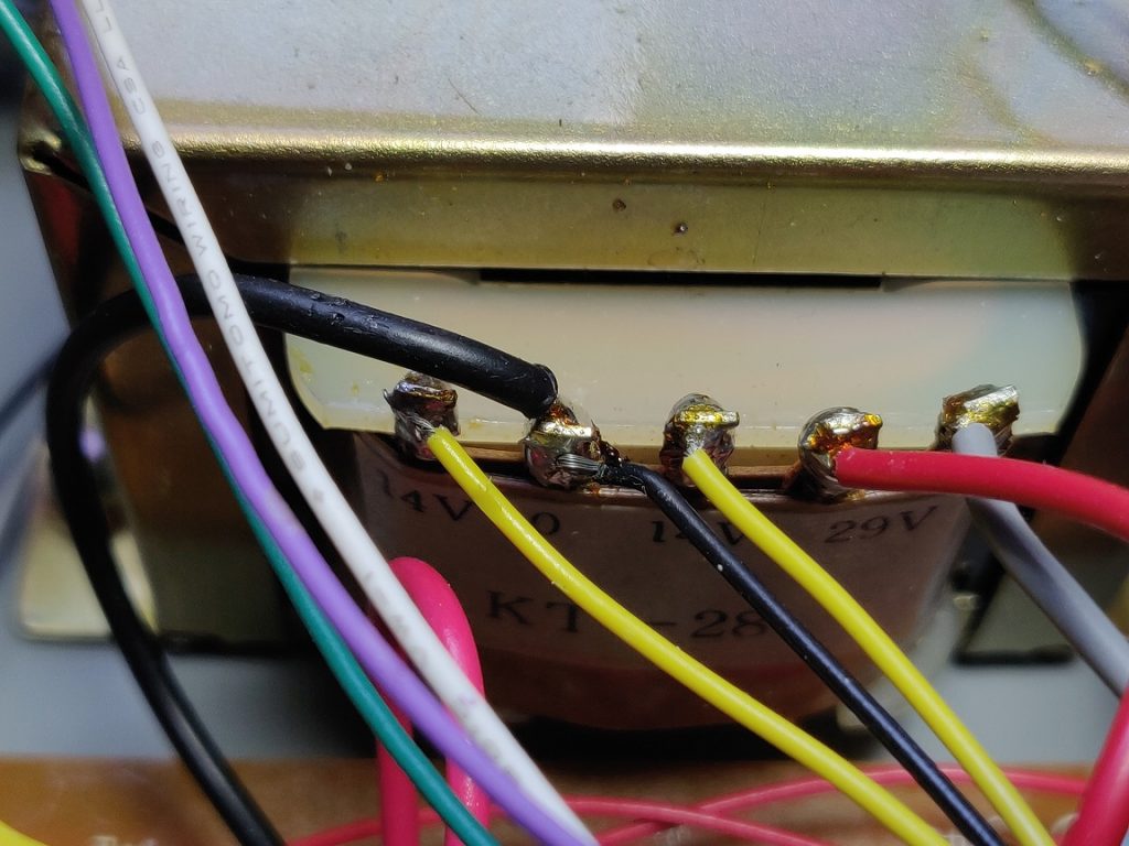
Ground L7812 to 0V 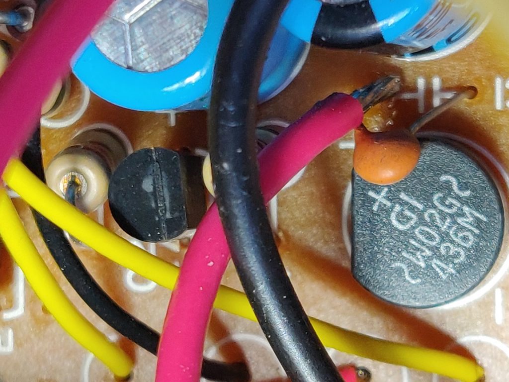
Input L7812 to bridge rectifier. 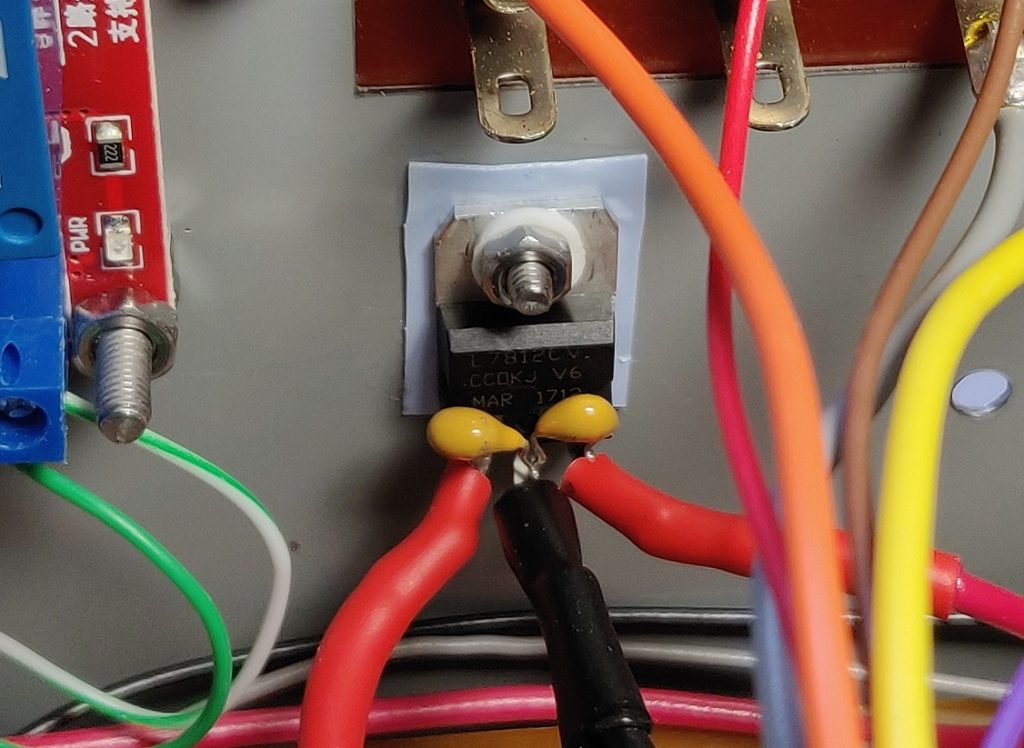
L7812 mounted on rear of the controller.
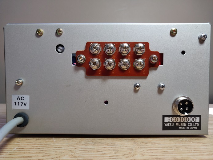
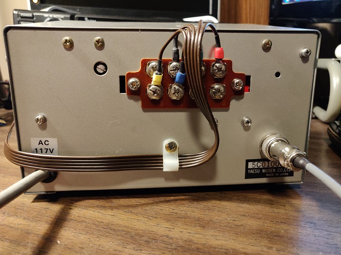
To make the connections to the ST2-USB controller I used a 4 pin microphone connector. There may be better options, but that is what my junque box had and it seems very well suited for this application. This connector will carry the left and right signals from the controller and provides the feedback voltage from the Yaesu controller to the ST2-USB controller. The last, and fourth, pin is used to connect the common ground.
Please refer to the complete schematic to see how all the connections need to be made between the various parts and the Yaesu controller. Below is a selection of images that will give you an idea on how to mount and wire everything.
Remote control of the Yaesu G-450XL rotator is possible with these modifications. It will interface just fine with the Fox Delta ST2-USB controller. I use it with Raspberry 4B running Gpredict to have the antennas track the satellites. I’ve been using this for over a year now and it has worked flawlessly.